In the previous post, we discussed setting up AddBiomeachanics for local data analysis. In this post, we’re going to from freshly collected laboratory data to motion reconstructions in OpenSim or AddBiomechanics. The Kuopio Gait dataset and Kuopio Full-Body (KFB) dataset were both collected in the HUMEA laboratory at the University of Eastern Finland. Using this data in downstream processing application, like OpenSim, requires preprocessing from the laboratory coordinate system and units to OpenSim’s coordinate system and units.
Extracting Data
For optical motion capture, Vicon Nexus records data in the .c3d file format. This single file contains all the data channels recorded by the Vicon trial for a single capture. For inertial measurement units (IMUs), the Xsens MT Manager records data in an .mtb file format. The extraction pipeline which processes both file types for the KFB dataset is available here.
For .c3d file extraction, it is important to set the following option in order to properly calculate the center of pressure (COP):
OpenSim::C3DFileAdapter c3dFileAdapter{};
c3dFileAdapter.setLocationForForceExpression(OpenSim::C3DFileAdapter::ForceLocation::CenterOfPressure);
Unfortunately, Zenodo does not allow for editing uploaded files. This means that the extraction pipeline needs to be rerun from the .c3d stage in order to obtain COP data for the dataset.
Preprocessing
After data extraction, there will be <TRIAL>_markers.trc and <TIRAL>_grfs.sto files for each trial. We will use the trial walking from the KFB dataset for the remainder of this post (walking_markers.trc and walking_grfs.sto. The trial includes treadmill walking for a duration of 60 seconds. To begin, we will setup a C++ project which uses OpenSim installed on the system or built from source. A plethora of examples of this project structure can be found here.
To work with OpenSim, the markers need to be rotated to match the OpenSim coordinate system (see this issue for more) and the force plate data needs to be mapped so that the correct components of force match the OpenSim coordinate system. Additionally, the laboratory is configured with distances in millimeters (mm) and OpenSim expects distances in meters (m). The main.cpp file which performs these steps is outlined as follows:
#include <Common/CommonUtilities.h>
#include <Common/TimeSeriesTable.h>
#include <algorithm>
#include <cstdlib>
#include <iostream>
#include <string>

#include <OpenSim/Common/C3DFileAdapter.h>
#include <OpenSim/Common/IO.h>
#include <OpenSim/Common/STOFileAdapter.h>
#include <OpenSim/Common/TRCFileAdapter.h>
#include <OpenSim/Simulation/TableProcessor.h>
#include <SimTKcommon/Simmatrix.h>
#include <utility>

void rotateMarkerTable(OpenSim::TimeSeriesTableVec3 &table,
                       const SimTK::Rotation &R) {
  size_t nt = table.getNumRows();
  // Rotate table
  std::vector<size_t> row_indicies(nt);
  std::iota(row_indicies.begin(), row_indicies.end(), 0);
  std::for_each(
      row_indicies.begin(), row_indicies.end(), [&table, &R](size_t i) {
        auto row = table.updRowAtIndex(i);
        std::transform(row.begin(), row.end(), row.begin(),
                       [&R](const SimTK::Vec<3> &v) { return R * v; });
      });
  return;
}

void extractGRF(OpenSim::TimeSeriesTable &table,
                const std::string right_foot_col,
                const std::string left_foot_col) {
  const std::unordered_map<std::string, std::string> remap = {
      // this is here so time doesn't get deleted
      std::make_pair("time", "time"),
      std::make_pair("f" + right_foot_col + "_2", "R_ground_force_vx"),
      std::make_pair("f" + right_foot_col + "_3", "R_ground_force_vy"),
      std::make_pair("f" + right_foot_col + "_1", "R_ground_force_vz"),
      std::make_pair("p" + right_foot_col + "_2", "R_ground_force_px"),
      std::make_pair("p" + right_foot_col + "_3", "R_ground_force_py"),
      std::make_pair("p" + right_foot_col + "_1", "R_ground_force_pz"),
      std::make_pair("m" + right_foot_col + "_2", "R_ground_torque_x"),
      std::make_pair("m" + right_foot_col + "_3", "R_ground_torque_y"),
      std::make_pair("m" + right_foot_col + "_1", "R_ground_torque_z"),
      std::make_pair("f" + left_foot_col + "_2", "L_ground_force_vx"),
      std::make_pair("f" + left_foot_col + "_3", "L_ground_force_vy"),
      std::make_pair("f" + left_foot_col + "_1", "L_ground_force_vz"),
      std::make_pair("p" + left_foot_col + "_2", "L_ground_force_px"),
      std::make_pair("p" + left_foot_col + "_3", "L_ground_force_py"),
      std::make_pair("p" + left_foot_col + "_1", "L_ground_force_pz"),
      std::make_pair("m" + left_foot_col + "_2", "L_ground_torque_x"),
      std::make_pair("m" + left_foot_col + "_3", "L_ground_torque_y"),
      std::make_pair("m" + left_foot_col + "_1", "L_ground_torque_z"),

  };
  const auto &labels = table.getColumnLabels();

  size_t nt = table.getNumRows();

  for (size_t i = 0; i < labels.size(); ++i) {
    const auto label = labels.at(i);
    std::cout << label << std::endl;
    // https://stackoverflow.com/a/55482091
    if (auto it{remap.find(label)}; it != std::end(remap)) {
      // Use `structured binding` to get the key and value.
      const auto &[key, value]{*it};
      std::cout << "Renaming: " << key << " to: " << value << std::endl;
      table.setColumnLabel(i, value);

      if (value.find("torque") != std::string::npos ||
          value.find("force_p") != std::string::npos) {
        // Converting from Nmm to Nm
        table.updDependentColumnAtIndex(i) =
            table.getDependentColumnAtIndex(i) / 1000;
      }
    }
  }
  // Second because the indexing gets jacked up if you mutate the columns in the
  // first pass
  for (const auto label : labels) {
    if (auto it{remap.find(label)}; it == std::end(remap)) {
      // Key was not found..
      std::cout << "Removing key: " << label << std::endl;
      table.removeColumn(label);
    }
  }

  return;
}

void preprocess() {
  const std::string trial = "walking";
  const std::string trial_markers = trial + "_markers.trc";
  const std::string trial_markers_output = "markers.trc";
  const std::string trial_grfs = trial + "_grfs.sto";
  const std::string trial_grfs_output = "grf.mot";

  const std::string right_foot_col = "5";
  const std::string left_foot_col = "4";

  const double startTime = 25.0;
  const double endTime = 30.0;

  // Rotate each marker in the marker table
  // See https://github.com/opensim-org/opensim-core/issues/4146
  std::cout << "Processing: " << trial_markers << std::endl;
  OpenSim::TRCFileAdapter trcfileadapter{};
  OpenSim::TimeSeriesTableVec3 table{trial_markers};
  const SimTK::Vec3 marker_rotations(-SimTK::Pi / 2, SimTK::Pi / 2, 0);
  const SimTK::Rotation sensorToOpenSim =
      SimTK::Rotation(SimTK::BodyOrSpaceType::SpaceRotationSequence,
                      marker_rotations[0], SimTK::XAxis, marker_rotations[1],
                      SimTK::YAxis, marker_rotations[2], SimTK::ZAxis);

  rotateMarkerTable(table, sensorToOpenSim);
  table.trim(startTime, endTime);
  trcfileadapter.write(table, trial_markers_output);
  std::cout << "Wrote: " << trial_markers_output << std::endl;

  std::cout << "Processing: " << trial_grfs << std::endl;
  OpenSim::STOFileAdapter grffileadapter{};
  OpenSim::TimeSeriesTable grfTable{trial_grfs};
  extractGRF(grfTable, right_foot_col, left_foot_col);
  grfTable.trim(startTime, endTime);
  grffileadapter.write(grfTable, trial_grfs_output);

  std::cout << "Wrote: " << trial_grfs_output << std::endl;
}

int main() {
  preprocess();
  return EXIT_SUCCESS;
}
This script is specifically designed to make data compatible for use with AddBiomechanics which expects each trial to be contained in a folder which has a markers.trc and grf.mot file. For file formats, .mot and .sto files are almost exactly the same but subtly different in confusing ways. Supposedly, .sto files are uniformly spaced and contain time in the first column.
If you are tasked with converting data from your laboratory into a format compatible with OpenSim, it is important to understand the OpenSim coordinate system. It is easier for me to identify and assign the components by common sense than by anatomical terms, but if you prefer that here is an official explanation.
In OpenSim the Y-Axis is up, so the largest component of force (in our case f5_3) is the y component. This is the primary component of force generated by walking. The second largest component of force is the side-to-side motion (in our case f5_2) which corresponds to the X-Axis in OpenSim. Finally, the smallest component of force is the “stanky leg” motion (in our case f5_3) which corresponds to the Z-Axis in OpenSim. The torques/moments should follow the same convention (so m5_3 would become the Z component of torque`). When visualizing the forces, you should be able to easily assign them by looking at the magnitudes during a step.
The marker data needs to be transformed so that when you load a .osim model, the marker point cloud is aligned with the skeleton. Our default configuration makes it so that the point cloud is walking from within the ground, out to the light and then into the ceiling, through the roof and eventually into space. Subsequent processing works much better when the markers and OpenSim model are aligned. Determining the correct rotation sequence can be determined by opening the OpenSim GUI and trying every possible rotation sequence until the point cloud is aligned in a way that makes sense. In our case this rotation in XYZ Euler angles is (-90°,-90°,0°).
If using IMU data, that also needs to be transformed, as with the marker cloud via the guess and check method. When doing this, the pelvis IMU should visually appear the same way as it was attached to the participant. There are only two valid rotations which produce this configuration and one is easy to rule out if the model begins producing implausible motions.
Using AddBiomechanics
Now that AddBiomechanics is running locally and we have sufficiently preprocessed our data, we are ready to put all the pieces together. AddBiomechanics expects projects to be structured with a root folder (let’s call it my_project) which contains a _subject.json file, a unscaled_generic.osim model, and a trials folder. The project structure can be found here.
The model file needs to contain the specific marker set used in the markers.trc. I have also found that it works better if you attach all markers on the foot to one foot body (in this case the calcn_l or calcn_r body). You can use OpenSim Creator to help create the marker set. For AddBiomechanics, the model has to be differentiable so most OpenSim models will not work out-of-the-box to my understanding.
The _subject.json file is structured as follows:
{
  "subjectTags": [
    "healthy"
  ],
  "sex": "unknown",
  "massKg": "75.2",
  "heightM": "1.829",
  "email": "you@email.com",
  "skeletonPreset": "custom",
  "disableDynamics": true,
  "footBodyNames": [
    "calcn_r",
    "calcn_l"
  ],
  "shiftGRF": false,
  "maxTrialsToSolveMassOver": 4,
  "runMoco": false,
  "trialRanges": {
    "walk": [25.0, 30.0]
  }
}
The disableDynamics and runMoco flags control dynamics, which are disabled for now to illustrate the inverse kinematics portion. I have not yet been able to get dynamics working, which I will describe shortly.
Now that you have the model and the configuration file setup, create the trials directory. Within it, create subdirectories for each trial which match the trial names. Then in those directories, place the markers.trc and grf.mot files. These filenames are hard coded and you cannot use any other filename or extension.
After this, you can run AddBiomechanics from the server/engine directory with python src/engine.py ~/data/my_project assuming you created your data folder in the directory ~/data/my_project where ~ represents your home directory. It is also wise to backup your original data folder which they illustrate with this simple test script:
#!/bin/bash
set -e

TEST_NAME="my_test"

CURR_DIR=`pwd`
echo $CURR_DIR
rm -rf $CURR_DIR/tests/data/${TEST_NAME}
cp -r $CURR_DIR/tests/data/${TEST_NAME}_original $CURR_DIR/tests/data/${TEST_NAME}
echo $CURR_DIR
python src/engine.py $CURR_DIR/tests/data/${TEST_NAME}

# Print the last return value
echo $?
AddBiomechanics Results
If AddBiomechanics ran successfully, you should now see a folder called osim_results in the project directory. It contains subfolders called ID, IK, MarkerData, MOCO, and Models. We are interested in IK and Models since we did not run dynamics. The models folder will contain a model called match_markers_but_ignore_physics.osim which represents the best model fit for the data after running only inverse kinematics. The IK folder contains the data as well as .pdf results of marker error and the joint angles from the inverse kinematics simulation.
The Woes of Dynamics
If you have gotten this far, that is exciting. It means that you have already calculated inverse kinematics for custom data using AddBiomechanics. At this point, I went down a long and winding rabbit hole trying to get dynamics to function properly. Along the way, I learned more than I thought I ever would about force plates.
To begin, there are many types of force plates which seem to be ambiguously described as “type X”. Perusing the ezc3d source code, I found that there are types 1,2,3,4,5,6,7,11,12, and 21. After figuring out that we have type 2 force plates, I googlewhacked an article that attempts to explain what that means.
I found that the force plate only measures 3 axes of force and 3 axes of moments. Somehow the output also includes a center of pressure estimate which is calculated by the software based on the force plate geometry. In ezc3d this is calculated as for a type 2 force plate:
  for (size_t j = 0; j < 8; ++j) {
    ch[j] = subframe.channel(channel_idx[j]).data();
  }
  // CalMatrix (the example I have does not have any)

  force_raw(0) = ch[0] + ch[1];
  force_raw(1) = ch[2] + ch[3];
  force_raw(2) = ch[4] + ch[5] + ch[6] + ch[7];

  moment_raw(0) = _origin(1) * (ch[4] + ch[5] - ch[6] - ch[7]);
  moment_raw(1) = _origin(0) * (ch[5] + ch[6] - ch[4] - ch[7]);
  moment_raw(2) =
      _origin(1) * (ch[1] - ch[0]) + _origin(0) * (ch[2] - ch[3]);
  moment_raw += force_raw.cross(ezc3d::Vector3d(0, 0, _origin(2)));

_CoP[cmp] = _refFrame * CoP_raw + _meanCorners;
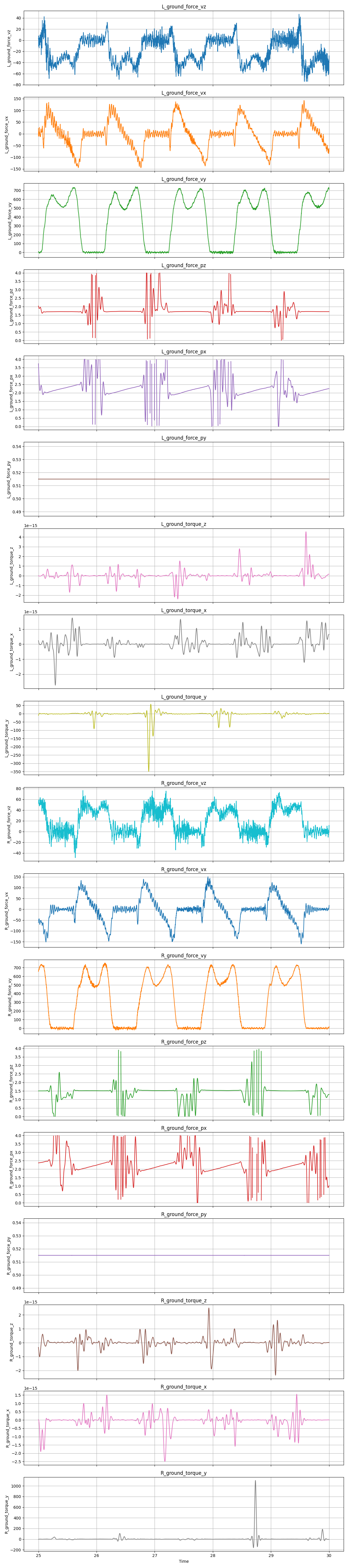
The works fine when there is sufficient force on the force plate during a step but goes completely haywire when the foot is off the belt in the swing phase. The very small force and moment values at this stage cause the COP estimate to explode. Additionally, measurement noise can cause an enormous torque value which creates insane COP values.
With a 20Hz low pass filter, the results look better but this still isn’t sufficient for the enormous torque spike near the 28.5 second mark for the right foot.
The following can be added to the preprocessing code to clamp the values to a reasonable limit for the given force plate:
  const auto &new_labels = table.getColumnLabels();

  for (size_t i = 0; i < new_labels.size(); ++i) {
    const auto label = new_labels.at(i);
    auto column = table.updDependentColumnAtIndex(i);
    if (label.find("torque") != std::string::npos) {
      const double torque_threshold = 100;
      std::cout << "Clamping: " << label << " between: +/- " << torque_threshold
                << std::endl;
      for (auto &value : column) {
        value = std::clamp(value, -torque_threshold, torque_threshold);
      }
    }
    if (label.find("_px") != std::string::npos) {
      const double px_low = 1.75;
      const double px_high = 2.75;
      std::cout << "Clamping: " << label << " between: " << px_low << " and "
                << px_high << std::endl;
      for (auto &value : column) {
        value = std::clamp(value, px_low, px_high);
      }
    }
    if (label.find("_pz") != std::string::npos) {
      const double pz_low = 1;
      const double pz_high = 2;
      std::cout << "Clamping: " << label << " between: " << pz_low << " and "
                << pz_high << std::endl;
      for (auto &value : column) {
        value = std::clamp(value, pz_low, pz_high);
      }
    }
  }
The following code produces these results where you can clearly see the misbehavior of the COP and torque estimates when the foot is off the belt:
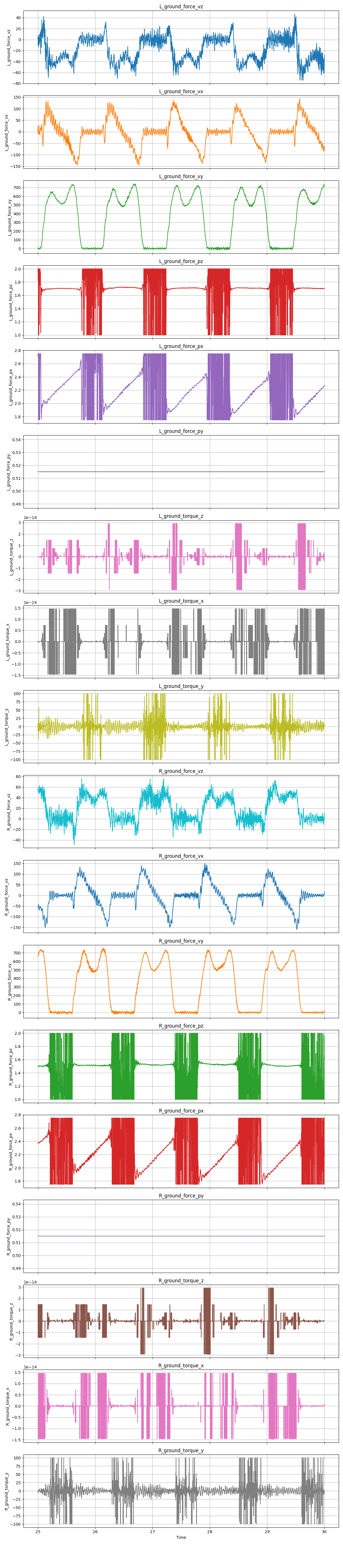
At this point the force plates can be understood by AddBiomechanics. The signals don’t look good but at least they somewhat make sense now. Nonetheless, this still produced a problem which read “force-weighted center-of-pressure-outside-of-foot error of 2.69 meters, which is higher than the threshold of 0.01m.” This seems suspiciously like the distance from the origin to the treadmill, but I will lay the dynamics saga to rest for now.